Parts Identification
Front View
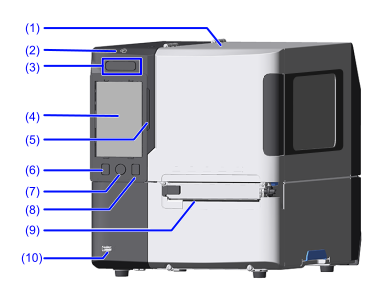
- Top cover
Open this cover when replacing consumables or cleaning the product. - NFC antenna location
When communicating with an NFC-enabled mobile device, hold the mobile device here. -
 Power button
To power on the product, press thebutton until the LED indicator lights blue.
To power off the product, press thebutton for more than 2 seconds, and then tap [Power off]. The LED indicator lights red, then turns off and the power is turned off.

- Enabling [System] > [Start on AC] allows the product to be powered on or off via the main power supply connected to the product.

- Do not disconnect the power cord until the powering off process is completed on the product.
- An incorrect power on/off operation may damage the product settings. It is always recommended to use the power button to allow proper shutdown of the product and ensure changes made to menu settings are saved appropriately.
- Do not power off the product during operation, such as when printing or updating. Doing so could cause a malfunction of the product.
- Touch Panel
Shows the status of the product, error messages, menu items, and more. The display is operated by touching it with your finger.
- Do not operate the display with pointed or sharped objects such as mechanical pencils or ballpoint pens. Doing so could damage the display or result in electric shock.
- LED Indicator
Indicates the current status of the product. -
 Online/Offline button
Switches between Online mode and Offline mode. -
 Home button
Move to the Home Screen.
For more information on the Home Screen, see Displays and Operations in the Home Screen. -
 Feed button
Feeds the media. - Media discharge outlet
Discharges the printed media. - USB connector (Type A)
Connect USB devices, like a USB memory, scanner, or keyboard.
- Use a USB memory whose volume label contains only single-byte alphanumeric characters. Volume labels with double-byte characters are not supported.
- Connection via a USB hub is not supported.
- Format the USB memory in FAT32 before use.
Rear View

- SIM communication unit (
 option)
This unit is needed to use SIM communications (cellular) for the SOS (SATO Online Services) function. Use the black antenna. - Wireless LAN/Bluetooth unit (option)
This unit is needed to use wireless LAN and Bluetooth. Use the green antenna. - USB connector (Type A)
Connect USB devices, like a USB memory, scanner, or keyboard. - USB connector (Type B)
Connect USB cables. To connect the product to the computer using the USB interface. - LAN connector
Connect LAN cables. - RS-232C connector (
option,
 standard equipment)
Connect RS-232C cables. To connect the product to the computer using the RS-232C serial interface.
Also, a scanner can be connected.
- Printing using the USB serial conversion cable is not guaranteed, so be sure to use the recommended RS-232C cable.
- To connect and use a scanner, you must change the setting to [RS-232C] in [Printing] > [Advanced] > [Barcode Checker] > [Interface].
- EXT connector (
option,
standard equipment)
Connect a cable for external signals. Used to connect an external device to the product. - AC input terminal
Connect the power cord.
- When connecting the power cord, be sure to connect the ground wire to the ground terminal. Electric shock could occur if you do not. Also, product operations could be affected by interference from electrical noise.
Internal View
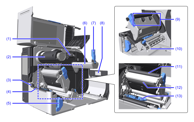
- Ribbon supply spindle
Load the ribbon here. - Ribbon rewind spindle
This is the part that winds up the used ribbon. - Label top sensor
When the Label Waste Prevention function is enabled, this sensor detects the leading edge of the media and aligns the media to the print start position. - Platen roller (consumable part)
This part presses the media and print head together and feeds the media. - Head lock lever
Press this lever backward to open the head assembly to replace media, etc. - Media roll holder
Load the media roll here. - Media roll holder guide
Adjust to the width of the media being used. - Sticker
Shows information about the product, such as model name and serial number.
The 8-digit alphanumeric number to the right of "S/N" is the serial number. - Head Pressure Adjustment Dial(s)
Adjust the pressure balance of the print head according to the thickness and width of the media you are using.
For more information, refer to Adjusting the Head Pressure Balance. - Media Guide
Align the position of the media guide to the width of the media you are using. - Ribbon Roller
This is the part that feeds the ribbon. - Print head (consumable part)
This is the part that prints directly on the media or uses a ribbon. - Media sensor guide
Use to adjust the position of the media sensor.
For more information, see Adjusting the Position of the Media Sensor.