Setting Up Connections
Setting the Wired LAN/Wireless LAN
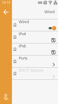
When Using Wired LAN
Tap [Network] > [Wired] > [Wired] to enable it, and then configure the network settings such as the IP address. (Initial value: Disabled)
For more information, see Configuring Network Settings.
When Using Wireless LAN
This can be used when the wireless LAN/Bluetooth unit is installed.
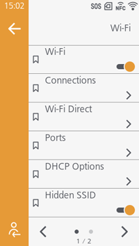
Tap [Network] > [Wi-Fi] > [Wi-Fi] to enable it, and then configure the network settings in [Connections]. (Initial value: Disabled)
For more information, see Configuring Network Settings.
If necessary, change the Hidden SSID function (initial value: Enabled) and frequency band (initial value: [All]) settings.
Setting Up a USB Connection
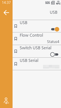
Configure settings related to USB. (Initial value: Disabled)
Before setting up the product, enable [Switch USB Serial] to return the USB serial number, allowing you to replace the product without adding a new printer driver.
If [Switch USB Serial] is disabled, the factory-set USB serial number (unique to each product) will be returned, and you need to configure the printer driver settings for each product.
The USB serial number can be confirmed in [USB Serial].
Initial value:
- [Flow Control]: [Status4]
- [BCC]: Disabled
- [Switch USB Serial]: Disabled

- If two products that have the same USB serial number are connected to the same computer, a blue screen error may occur on the computer.
Setting Up a Bluetooth Connection
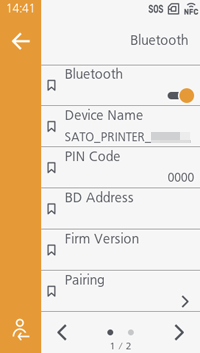
Configure settings related to Bluetooth. (Initial value: Disabled)
Set the device name, PIN code, host BD address, and authentication level.
This is shown when the wireless LAN/Bluetooth unit is being used.
Search for a Bluetooth device and show the name of the device in [Pairing] > [Search Devices].
When you execute [Pairing] > [Pairing Standby], the host can detect the product as a printer available for pairing.
Initial value:
- [Device Name]: SATO PRINTER_xxxxxxxxxxxx
- [PIN Code]: 0000
- [Sniff]: Enabled
- [Security]: [Level 4]
- [CRC Mode]: Disabled
- [Flow Control]: [Status4]
- If pairing fails, the pairing information from the previous paring may be remained on the product’s side. Delete the product’s pairing information from [Paired Devices] and then try pairing again.
Setting Up a NFC Connection
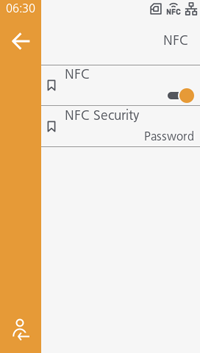
Configure settings related to NFC. (Initial value: Disabled)
When NFC is enabled, the printer operates as an NFC tag for printer configuration and information retrieval when the power is off. When the power is on, NFC allows small data communication and Bluetooth/Wi‑Fi handover connections.
In [NFC Security], configure the behavior when settings are written by touching an NFC‑enabled device to the printer. (Initial value: [Password])
- [Confirm]
A confirmation screen is displayed. - [Password]
A password is required.

- If it does not communicate well, shift the device to the front, back, left and right, and then hold it up again.
- For the operation of the NFC for the device, refer to the user manual for the device.
Setting Up an RS-232C Connection
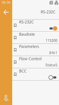
Configure settings related to RS-232C. (Initial value: Disabled)
Configure data transfer rate (bps) and parameters.
This appears if the interface expansion board is installed.
If [RS-232C] is displayed in [Barcode Checker], the scanner used for the barcode check function is configured to connect via the RS-232C port. Verify the communication interface used for the barcode check function.
Parameter Configurations List
| Parameter | Data Length (Bits) | Parity |
Stop bit (bit) |
|---|---|---|---|
| 8-N-1 | 8 | NONE | 1 |
|
8-O-1 |
8 | ODD | 1 |
| 8-E-1 | 8 | EVEN | 1 |
| 8-N-2 | 8 | NONE | 2 |
| 8-O-2 | 8 | ODD | 2 |
| 8-E-2 | 8 | EVEN | 2 |
| 7-N-1 | 7 | NONE | 1 |
| 7-O-1 | 7 | ODD | 1 |
| 7-E-1 | 7 | EVEN | 1 |
| 7-N-2 | 7 | NONE | 2 |
| 7-O-2 | 7 | ODD | 2 |
| 7-E-2 | 7 | EVEN | 2 |
Initial value:
- [Baudrate]: 115200
- [Parameters]: [8-N-1]
- [Flow Control]: [Status4]
- [BCC]: Disabled
- When using the READY/BUSY control, make sure that the product is in power on mode before you send the data from the host.
- With communication protocols such as XON/XOFF, Status3, Status4 or Status5, a receive buffer full error will occur when the received data is more than the receive buffer size (3.00 MB). When sending data, monitor the status of the product and keep the size of the data that is sent to less than 3.00 MB.
- A parity error is detected when an error occurs after receiving the start code <A> command.
Setting Up an External Signal Connection
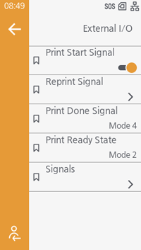
Configure settings related to external signal.
This appears if the interface expansion board is installed.
- Refer to the SBPL Command Reference for external signal pinout tables and timing charts.
- Please disable the sleep mode when using external signals. Regarding the sleep mode, see Setting the Time to Transition to Sleep Mode.
[Print Start Signal]
[Reprint Signal] > [Reprint Signal]
[Print Done Signal]
[Print Ready State]
[Signals] > [Input Signal]
[Signals] > [Output Signal]
Setting Up a SIM Connection (Cellular)

By using a SIM connection (cellular), SOS services (SATO Online Services) can be used in environments where there is no network connection.
If you require a SIM connection (cellular), contact your technical support (dedicated SOS contact).
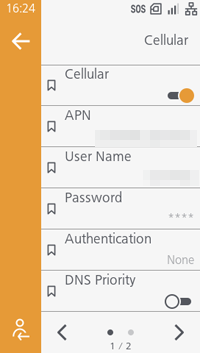
This appears when the SIM communication unit is installed.
When SIM connection (cellular) is enabled, you can see the access point name, user name, password, and authentication method.
The IP address used for SOS server communication is displayed in [IPv4].
Initial value:
- [Cellular]: Disabled
- [DNS Priority]: Disabled
Configuring Settings Common to All Interfaces
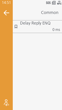
[Delay Reply ENQ]