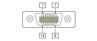
1 When using the 14-pin conversion cable, do not connect the power pin to "IN_COM" pin. The "IN COM" pin is connected to 5 V in cable.
2 These input signal terminals can be connected to the open collector input devices.
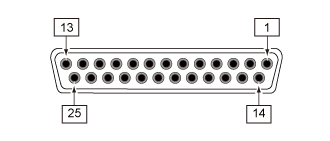
3 If 25-pin is selected, the total output of Pin No. 2 and 12 will be 600 mA.
1 When using the 14-pin conversion cable, do not connect the power pin to "IN_COM" pin. The "IN COM" pin is connected to 5 V in cable.
2 These input signal terminals can be connected to the open collector input devices.
3 If 25-pin is selected, the total output of Pin No. 2 and 12 will be 600 mA.